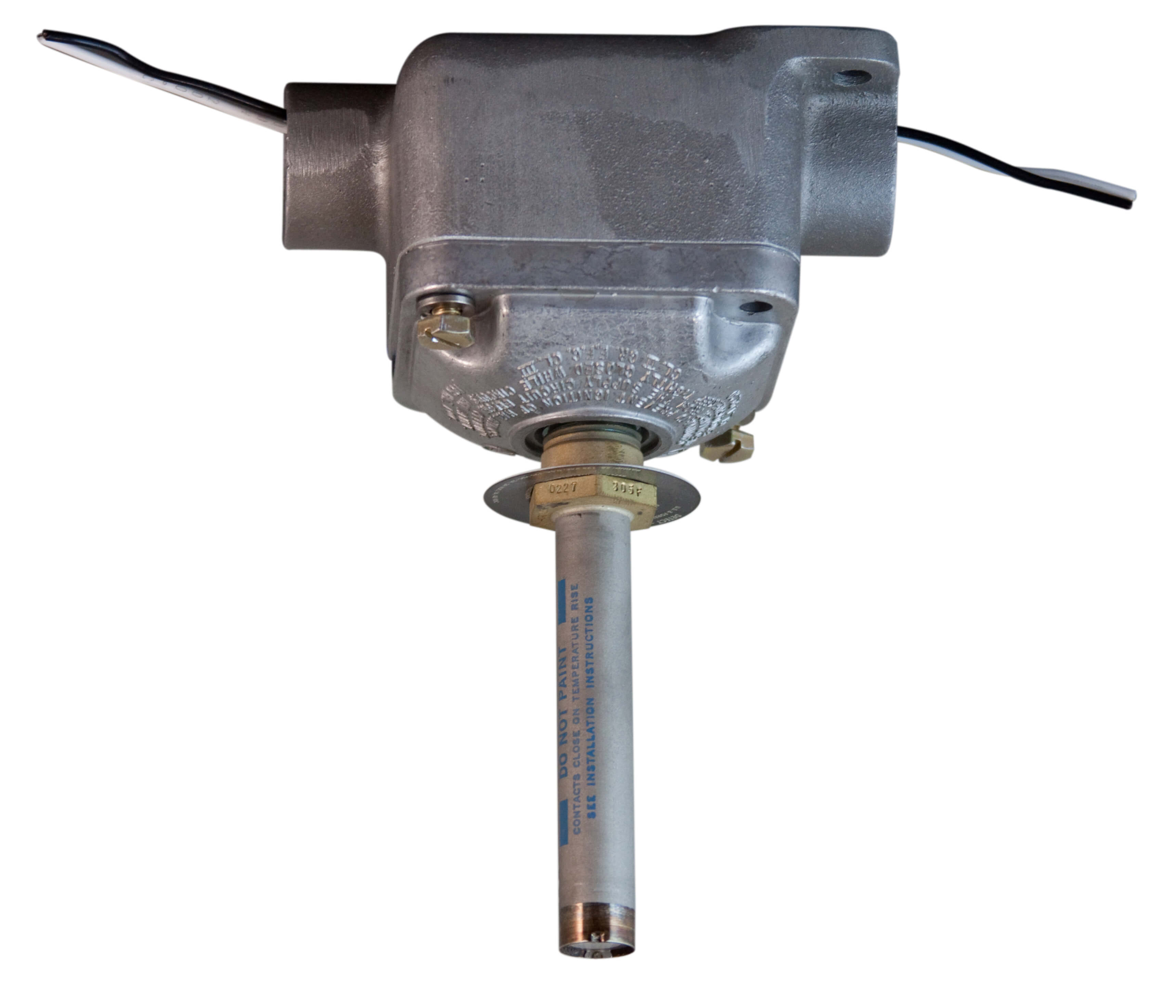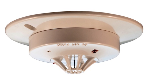
5010 Dual Channel Smoke/Fire Detection Input Modules are used to connect smoke detectors, heat detectors, manual fire stations, and any other contact-closing initiating devices to the control system.


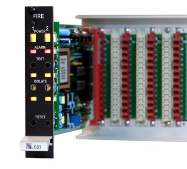
The SST Model 5010 Two Channel Smoke/ Fire Detection Module provides two independent detection input channels for the NOVA-5000 Detection and Control System. Each input circuit is designed for a two-wire “Class B” circuit, and can supply the operating voltage required to power Ionization and Photoelectric Smoke Detectors, while at the same time receiving alarm signals from these devices. Each alarm input module may also receive signals from any device that initiates a contact closure upon alarm, such as fixed temperature or rate-of-rise Heat Detectors and Manual Alarm Stations.
Any number of contact type input devices may be connected to the Model 5010 input circuit. However, when using detectors with active electronic circuits (such as smoke detectors), the number of detectors must be limited so that the total standby current drawn by the detectors does not exceed the capabilities of the module. Typically, up to 30 detectors can be used with the Model 5010 for each channel.
The operation of each of the two channels on the Model 5010 Smoke/Fire Detection Input Module is independent and identical. An Alarm Condition causes the module red LED to begin flashing, and the module alarm relay to be energized. There is also a separate Alarm Lamp output on the module which will be flashing, and can be used to drive an external lamp or LED. Also, a short pulse signal is sent on the main system alarm bus to initiate an external alarm signal. The lights continue to flash until the module receives an Acknowledge signal (typically from an external pushbutton); this causes the flashing lights to change to a steady on condition. The alarm circuits are “latching,” so that alarm indications and outputs remain until the Reset switch is depressed. During reset, the Power Status Output from the module is momentarily interrupted; this may be used to reset latching circuits in an external input unit, such as a Flame Detector.
An Isolate switch is provided for each channel to permit temporary deactivation of the channel outputs when desired. This switch is recessed so that a tool is required for its operation. When isolated, the yellow isolate LED will be lit. If the module alarm circuits are now tested, either by activating a field device, or by depressing the Alarm Test pushbutton on the module, the alarm LED and lamp output will function normally. However, the alarm relay and alarm bus outputs will not be activated. Depressing the Alarm test switch has no effect if the Isolate switch is not activated.
During normal operation, the wiring connected to the Model 5010 input terminals is continuously “supervised” for faults by passing a small current through an “End-of-Line” resistor located at the last field device connected to the input. The supervised circuit will cause the yellow fault LED’s to flash (until acknowledged) if any field wire is open, shorted, or grounded.
The Power systems for the two channels are independent, and failure of one will not affect the other. Any power failure will be indicated by illumination of the yellow power fault LED. In addition to the features noted above, all LED’s will be illuminated when the LAMP TEST bus input is activated. Each Model 5010 Module mounts in one plug-in space in the NOVA-5000 Rack Assembly.
Smoke/Fire detection capability shall be provided by plug-in module(s) having two independent detection channels per module. The module shall utilize a two-wire Class B circuit between the module and the detection devices, and be capable of supplying operating voltage to active devices over these two wires, while at the same time receiving alarm signals from the devices. The field installed wiring between the module and field device shall be continuously supervised, and a fault reported upon detection of any open circuit or connection to ground. A fault must also be reported if a short circuit occurs between the two field wires. Alarm and Fault conditions shall be indicated by LED’s on the front of the module. The LED’s shall flash when activated until an “acknowledge” signal is applied to the module, at which time any flashing LED’s shall change to a steady on indication. The module shall provide, for each channel, front panel mounted ISOLATE and ALARM TEST switches. These switches are to enable testing of the alarm circuits in the module without activating the system outputs from the module. Safety Systems Technology Model 5010 Two Channel Smoke/Fire Detection Modules, or approved equivalent, shall be supplied.
| Detection Inputs: | Two wire, supervised, Class B. Suitable for Ionization/Photoelectric Smoke Detectors, Manual Stations, Thermal Switches, etc. |
| Power Supply to Detectors: | 22 VDC @ 4.0 mA Total Standby current of all detectors must not exceed this amount. |
| Minimum Alarm Current: | 12 mA @ 22 VDC Detector must draw at least this much current when in alarm. |
| Alarm Relay Contacts: | 1.0 Amps @ 28 VDC Resistive Connect to 3 screw terminals on backplane, NO, COM, NC. |
| Alarm Lamp Output: | Open Collector current sink, 300 mA max. Follows state of alarm LED on module, Flashes on detection of an alarm, steady when acknowledged. |
| Power Status Output: | Open Collector current sink, 300 mA max. Momentarily interrupted when module is reset. Used to reset self-powered field devices with alarm latches. |
| Front Panel Indicators: | Power On, Power Fault, Alarm, Channel Isolated, Channel Fault All indicators are Light Emitting Diodes (LED’s). |
| Front Panel Switches: | Isolate, Reset, Alarm Test Alarm Test operable only when channel is in Isolate mode. |
| Module Power Requirement: | 24 VDC, 105 mA standby, 165 mA alarm. Total for two channels. Does not include any power drawn by smoke detectors. |
| Size: | 0.99 inch wide x 5.06 inches high x 7.4 inches deep Requires 1 mounting space in SST Standard Mounting Rack |
| Weight: | 7 ounces |
| PART NUMBER | DESCRIPTION |
| 35010 | Model 5010 Dual Channel Smoke/Fire Detection Input Module |
| 35381 | Package of 10 End-of-Line Resistors (2 resistors required for each Dual Channel Module) |
| 35360 | Module Calibration and Test Extender Card Recommended accessory for troubleshooting and adjusting calibration controls |


 Where to Buy
 +1 (949) 583-1857