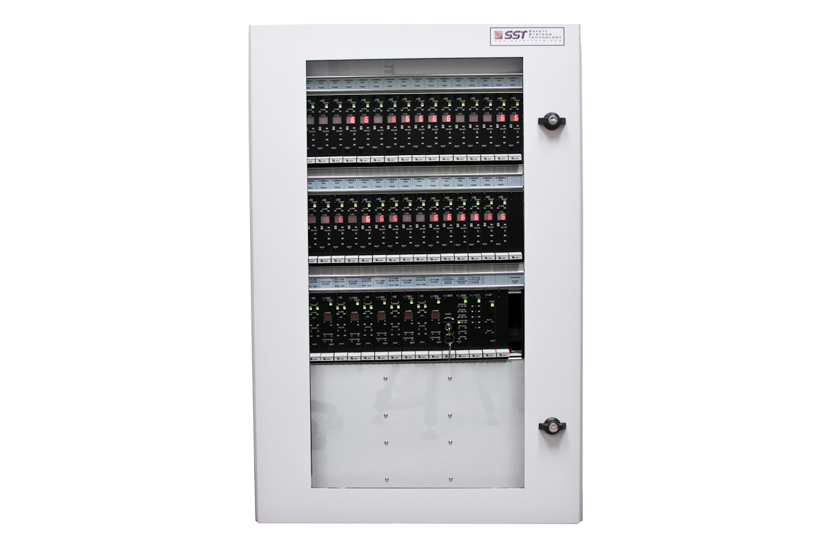
The VulcanGuard Gas Alarm Control Panel is a conventional modular gas detection control system to monitor all of your combustible gas, toxic gas, and oxygen deficiency/enrichment sensors and detectors. The system is customized for each installation by selecting from a number of different control modules to perform the required functions. The selected assortment of modules plug into one or more racks, which interconnect the modules to perform the required protection functions. 5 Year Warranty. Made in the USA.


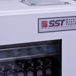
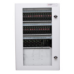
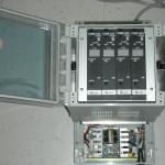
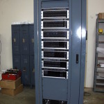
The VulcanGuard Gas Alarm Control Panel consists of a family of high performance, high reliability plug-in modules designed specifically for industrial, institutional and life safety applications. The required level of reliability is insured by a number of ingenious design approaches including extensive use of ASIC chips, industrial quality components, and design for operation under less-than-perfect power supply conditions. Each VulcanGuard Gas Alarm Control Panel is customized for the intended application by selecting the proper mix of System Modules. These System Modules, when assembled into a mounting rack, provide operating controls and indicator lights applicable to the required functions. The standard VulcanGuard Module Mounting Rack is a 5 inch high “Card Cage” designed for installation in a standard 19 inch EIA rack. Most of the VulcanGuard Modules are 1 inch wide, and the standard rack provides spaces for mounting sixteen 1 inch modules. A typical VulcanGuard System will provide for protection of one or more hazard areas. A printed circuit “back plane” is mounted on the rear of the rack for each of the hazard areas. This back plane interconnects the modules and also provides screw terminals for connection of the wires to field devices. Each module connects to the backplane via mating connectors. Connectors use gold contacts to insure reliable connections in industrial atmospheres. Modules may be inserted or removed from the rack with power on without any adverse effects. Each module space is keyed so that it will accept only the type of module for which it is wired. A retaining screw is provided on the front of the module for positive mounting. A VulcanGuard System consists of one or more module racks for each protected zone, plus the specific mix of modules as required to provide the protection for that zone. For zones requiring more than 16 modules, two or more racks may be interconnected together. The function of each module is clearlv and specifically indicated on the front panel of the module, so that operation of the VulcanGuard System during an emergency will be obvious to all personnel.
The Gas Control System shall be of modular construction. All modules shall be provided by a single manufacturer, and all shall be listed by at least one independent testing organization for use together in approved systems. The manufacturer shall have available modules for Gas Detection, Process Monitoring, Cross zoned or voted detection, Audible/Visual Alarming, and Control of Extinguishing Agents. All modules shall plug into standard 19″ wide, 5″ high mounting racks, and it shall be possible to setup the racks to accommodate any desired mixture of modules. Modules shall he keyed such that any replacement module can only be plugged into a space specifically assigned to that type of module. Module plug-in connectors shall utilize gold contact material to insure reliability with low level signals in corrosive atmospheres. The System shall be designed so that no spurious alarms or operations will he generated when any module is inserted or removed from the rack with power applied, and this shall be specifically stated in the manufacturer’s published data sheet. All inputs and outputs shall be protected against radio frequency and electromagnetic interference and power surges. The System shall be equipped with redundant power supplies to permit continuous operation upon failure of one supply. The System shall have a Subsequent Alarm feature, such that any active audible alarm signal which has been silenced will be reactivated upon generation of subsequent alarms. The Gas Detection and Control System shall be manufactured by Safety Systems Technology, Laguna Hills, California, their VulcanGuard Gas Alarm Control System, or approved equivalent. All detection, sensing and alarm devices shall be those supplied or recommended by Safety Systems Technology for use with their VulcanGuard Gas Alarm Control System.
| System Operating Voltage: | 16 to 32 Volts DC (24 VDC Nominal).
System will operate within specifications from any supply voltage within the specified range. All modules accept dual redundant supplies, but will operate with only one present. |
| Ambient Operating Temperature: | + 14 to + 140°F, – 10 to + 60°C
System maintains all specifications over this range. |
| RFI Characteristics: | No adverse system response when a 6 watt hand-held radio is operated within 1 foot of equipment.
Typical specification for industrial two-way radio. |
See individual data sheets for additional specifications applicable to each module and/or component.
See individual data sheets for each module and/or component

|
|
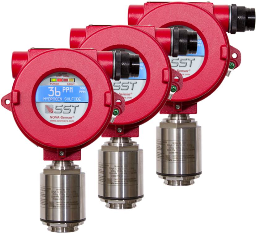
Combustible Gas Detectors |
|
Toxic Gas Detectors |
|
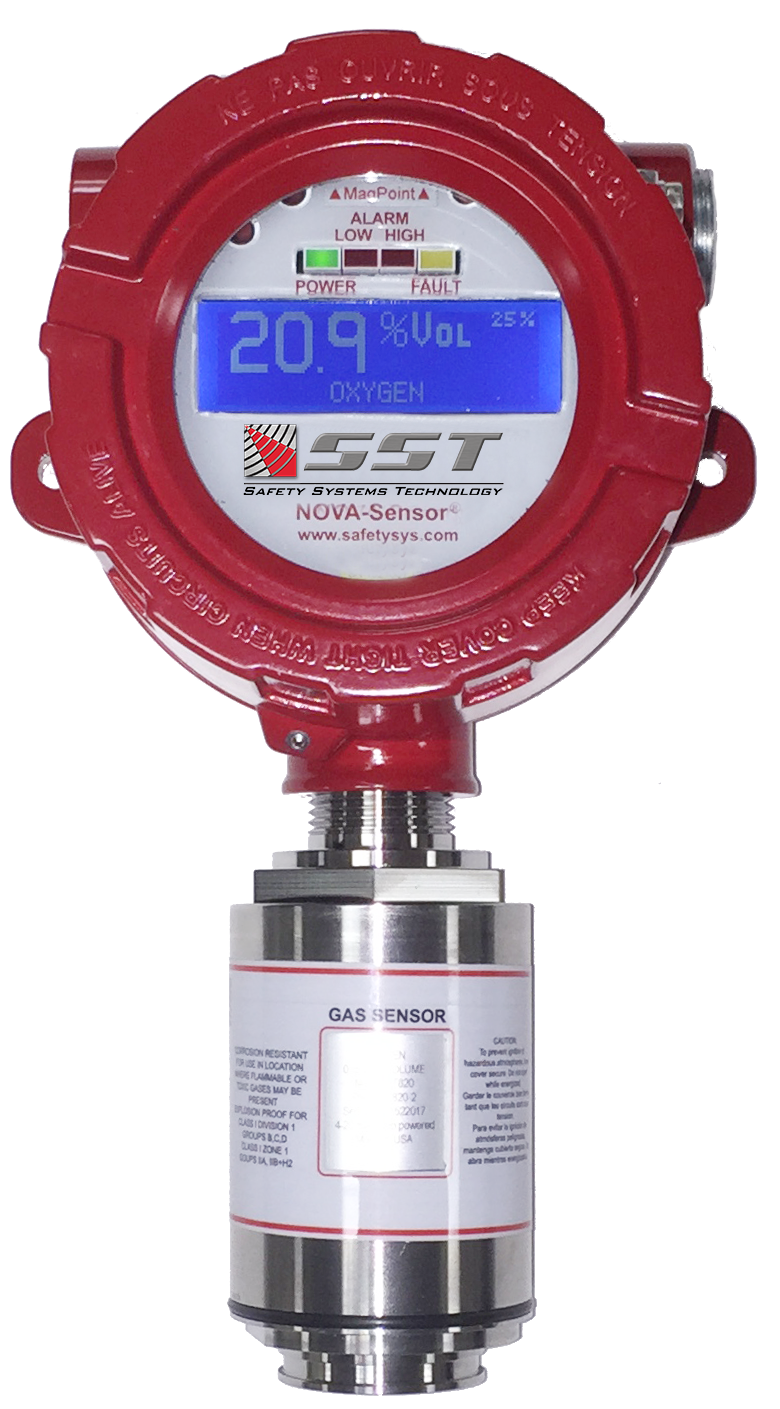
Oxygen Sensors |


 Where to Buy
 +1 (949) 583-1857