5241 Four Channel Supervised Alarm Output Module is used to provide 24 VDC operating voltage to external alarm devices, such as bells, horns, rotating beacons, strobe lights, etc. It may also be used to control other devices, such as shutdown relays, door closers, damper motors, or for elevator recall circuits.


The SST Model 5241 Supervised Alarm Output Module is used to provide 24 VDC operating voltage to external alarm devices, such as bells, horns, rotating beacons, strobe lights, etc. It may also be used to control other devices, such as shutdown relays, door closers, damper motors, or for elevator recall circuits. Field wiring is supervised for open circuits or short circuits by passing the supervisory current through an “end-of-line” device located at the last alarm appliance on each channel. The alarm appliances connected to any channel may be of different types, and the number of devices per channel is virtually unlimited, as long as the maximum current rating is not exceeded.
Each of the four identical channels on the Model 5241 can be individually configured for the desired operation. In most cases, the channel will be “hard-wired” to the output of another module in the NOVA-5000 System. Or the channel may be set to activate when any module in the system detects an alarm condition. Each channel may be set to be nonlatched or latched. In non-latched mode, the output of the Model 5241 channel will deactivate as soon as the channel input is deactivated. In latched mode, the output remains activated when the input signal is removed. The latched output will be deenergized when the NOVA-5000 System Acknowledge/Silence or Reset signal is activated.
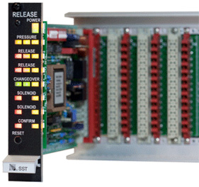
LED indicators on the front panel indicate the state of each of the four channels (energized or fault). Additional LED’s display the power supply and operational status of the module. There are no switches or operating controls on the front panel of the module.
Each Model 5241 Module mounts in one plug-in space in the NOVA-5000 Rack Assembly.
Alarm Output Signal capability shall be provided by plug-in module(s) having four independent alarm channels per module. The module shall continuously supervise the field wiring between the module and the field alarm devices for open circuits, short circuits, or ground faults. The module outputs shall be compatible with 24 VDC polarized output devices, and shall supervise field wiring for open or short circuits using a listed end-of-line device. LED indicators shall he provided on the module front panel to indicate alarm and fault status for each of the four channels, plus additional LED’s for power supply status. It shall be possible to independently program each channel to either latched or nonlatched operation. Safety Systems Technology Model 5241 Four Channel Supervised Alarm Output Modules, or approved equivalent shall be provided.
| Actuation Inputs: | Pulled up to +5 VDC via 100K ohm resistor Connect to 0 VDC common to actuate, or drive from output of other NOVA-5000 modules. |
| Alarm Outputs: | Four 24 VDC outputs rated at 2.0 amps each Supervised for open circuit or short circuit. |
| Channel Activation | By external signal or by NOVA-5000 System Alarm Signal Any output can be programmed to be latched or non-latched on deactivation |
| Front Panel Indicators: | Power On, Power Fault, Channel on (4), Channel Fault (4), Module Fault All indicators are Light Emitting Diodes (LED’s) |
| Power Requirement: | 24 VDC, 40 mA standby, 80 mA alarm Total for 4 channels. Does not include the power drawn by field devices |
| Size: | 0.99″ wide x 5.06″ high x 7.4″ deep Requires one mounting space in SST Standard Mounting Rack. |
| Weight: | 7 ounces |
| PART NUMBER | DESCRIPTION |
| 35241 | Model 5241 Four Channel Supervised Alarm Output Module |
| 35380 | Package of 10 End-of-Line Resistors (4 resistors required for each four channel module) |


 Where to Buy
 +1 (949) 583-1857