5230 Extinguishant Release Control Modules are used to activate solenoid valves for the release of extinguishing or inerting agent into a protected hazard area. The module is useable with all agents, including Carbon Dioxide, FM-200, FE-13, Novec 1230, Argonite, foam, and water deluge systems.


The SST Model 5230 Extinguishant Release Control Module is used to initiate the release of extinguishing or inerting agent in a protected hazard area. The module is available in several versions, all identical in operation, but with front panel markings indicating the type of extinguishing agent being used. The FE-13, FM-200 and CO2 modules are typically used to energize an electric solenoid which opens the valve on storage cylinders or tanks. The DELUGE and FOAM module is typically used to energize a small “pilot valve” which subsequently opens a large deluge valve to release water or foam spray into the protected area. For other types of releasing service, the module is available with suitable markings applied.
The Release Module is equipped with two separate inputs for initiating the releasing action. The “auto start” input is intended for automatic devices which initiate a request for extinguishant without human intervention. Devices with normally open alarm contacts, such as thermal heat detectors, Flame Detectors, or similar devices are usually considered reliable enough to connect directly to this circuit. In this application, the related field wiring is fully “supervised” for open circuits or short circuits. When using field detectors that are more prone to “false alarms,” such as Smoke or Combustible Gas Detectors, the auto input may be fed from other cross-zoned or voting modules in the NOVA-5000 system. A second input on the Release Module, the “manual start” input, is connected, via supervised field wires, to the Manual Release or “Pull” Stations, which start extinguishant release when operated by personnel in the protected area.
Separate Pre-release time delay circuits are provided for both the Auto Start and Manual Start circuits. Two DIP switches on the module permit setting the module to release agent immediately, or to delay the release for up to 4 minutes. The Model 5230 also includes two Inhibit inputs, one for the manual and one for the auto start inputs. These inhibit inputs are normally controlled by external bypass, abort, or isolate switches. Operation of these switches, prior to the occurrence of an alarm, prevents actual release of extinguishing agent, while permitting other alarm indicator lights and output circuits to operate normally. Or the inhibit input may be momentarily energized during the pre-release time delay; this will reset the timer to its full time delay setting.
When the start circuit has been energized, but not inhibited, the Auto Timing or Manual Timing output will be energized. This output may be used to control appropriate alarm signals or equipment shut downs. After the prerelease time delay has elapsed, the Release Control Module will apply 24 VDC actuating voltage to the releasing devices via supervised output circuits. To prevent excessive current drain when the system is operating from standby batteries, this actuating voltage may be removed after 4 seconds. (The associated release valve must latch open during this time.) Two independent output circuits are provided; the above described action normally occurs on Output A, which releases the Main extinguishing agent. For Main/Reserve systems, an external Changeover switch may be connected to the module. Operation of this switch transfers operation to Output B to release a Reserve extinguishing system.
Three additional inputs are provided on the Model 5230 Release Control Module for signals from field pressure switches. The Discharge Confirmed input is operated by a pressure switch located in the discharge piping, downstream from the discharge valve. Pressure at this point indicates that the valve has opened and extinguishant is being released. Two Extinguishant Pressure inputs can be fed from pressure switches in the cylinders or supply piping. An open switch indicates that pressure is present, ready for extinguishant release when requested. A closed switch indicates a leak or failure in the system. (The open/closed indications from the pressure switches can be interchanged by setting a DIP switch on the module.)
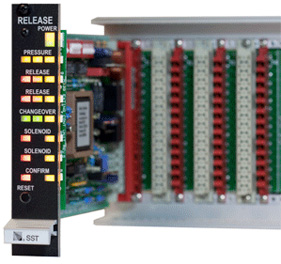
Two Green LED indicators are normally illuminated on the module front panel. The Power LED indicates that both of the redundant power supplies are operating within tolerance. The Changeover LED indicates whether protection will occur using extinguishing system A or B. Any alarm condition will cause the associated Red LED to flash, until acknowledged, then to change to a steady “on” condition. Alarm LED’s are provided for the auto start, manual start, discharge confirm, and extinguishant pressure inputs. Alarm LED’s are also provided to indicate when the A or B solenoids have been energized. During operation, as each alarm LED is lighted, the system alarm bus (on the module backplane) is also activated. Similarly, Yellow LED’s and a system fault bus indicate failures in the supervised field wiring associated with the module. Supervisory faults are displayed when any field wire is open or shorted.
Each Model 5230 Extinguishant Release Control Module mounts in one plug-in space in the NOVA-5000 System Rack Assembly. The module may be inserted into or removed from the rack with power applied without triggering the release of extinguishing agent.
System Alarm acknowledge, alarm reset and lamp test capability shall be provided by plug-in System Facility Module(s). The module shall include Light Emitting Diode (LED) lamps to indicate the presence of system alarm and system trouble conditions which have not been acknowledged. A dedicated system alarm output shall be provided, suitable for driving the inputs on compatible alarm output modules. The module shall also contain an internal system trouble audible signal which shall sound until system troubles are acknowledged. The System Facilities Module shall include a front panel mounted key operated two position rotary switch which can be assigned to any desired function. The operating kev shall be removable from the switch only when the switch is in the normal position. In systems with multiple System Facilities Modules, it shall be possible to have all switches operated by the same key, or to have different keys for each switch, as specified. In the latter case, there shall also be available a master key which will operate any of the system switches. Safety Systems Technology Model 5120 System Facilities Logic Modules, or approved equivalent, shall be supplied.
| Detection Inputs: | 2 provided, 4.4 mA @ 24 VDC supervisory current. Use with normally open contact devices. Suitable for use with heat or flame detectors, manual stations, or any other device with a dry contact output. May be operated in latching or non-latching mode. |
| Inhibit Inputs: | 2 provided, 24 VDC nominal. Normally open. Connect to DC common to inhibit associated Detection Input |
| Control Inputs: | 4 provided (Discharge Confirm, Main Extinguishant pressure, Reserve Extinguishant pressure, changeover), supervised. Normally open. Connect to DC common to activate. Confirm input may be set to latch on activation. |
| Release Solenoid Outputs: | 2 provided, 24 VDC @ 2 amp output, individually supervised. Provides 4 second pulse output to open extinguishant releasing valve. May optionally be set for coutinuous output. |
| Supervision: | Signals fault when any field wire is open or shorted Supervision of any input or output can he disabled via programming switches inside module. |
| Front Panel Indicators: | Power On, Power Fault, Extinguishant Pressure, Release start, Changeover, Solenoid Activated, Discharge Confirmed, Field Wiring Fault All indicators are Light Emitting Diodes (LED’s) |
| Front Panel Switch: | Reset Depressing Reset Switch also activates Lamp Test function. |
| Power requirements: | 24 VDC nominal, 90 mA standby, 140 mA alarm Does not include power drawn by release solenoids. |
| Size: | 0.99 inch wide, 5.06 inches high, 7.4 inches deep Requires 1 mounting space in SST Standard Mounting Rack. |
| Weight: | 7 ounces When installed. Shipping weight 14 ounces. |
| PART NUMBER | DESCRIPTION |
| 35230-2 | Model 5230 CO2 Release Control Module |
| 35230-3 | Model 5230 Deluge Release Control Module |
| 35230-3 | Model 5230 Deluge Release Control Module |
| 35230-4 | Model 5230 Foam Release Control Module |
| 35230-5 | Model 5230 Generic Release Control Module Legend reads “RELEASE”. Use for any application where identification of releasing agent is not required. |
| 36230-6 | Model 5230 FE-13 Release Control Module |
| 35230-7 | Model 5230 FM-200 Release Control Module |
| 35230-9 | Model 5230 with custom marking (special order) |
| 35380 | Package of 10 End-of-Line Resistors One resistor required for each supervised module input circuit. Maximum of 6 per module. |

|
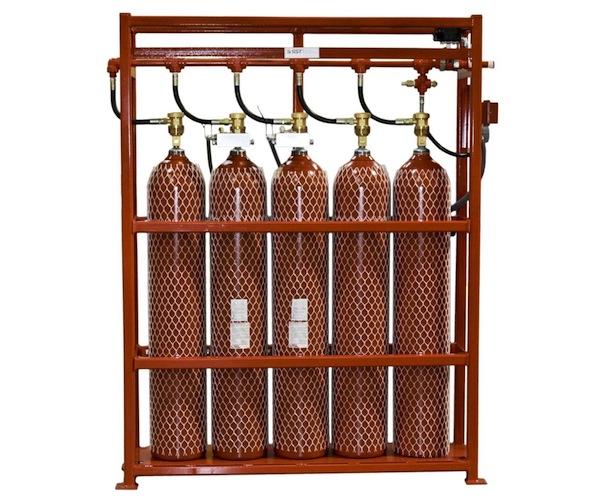
Model FS9600 Preassembled Fire Suppression & Extinguishing Skid |


 Where to Buy
 +1 (949) 583-1857