5120 System Facilities Logic Module is used to provide control capabilities common to all modules in a NOVA-5000 System. Pushbuttons on the module enable an alarm on any module to be acknowledged by an operator, alarm devices to be silenced, and all alarms reset. The control system can function without this module, if these capabilities are not required.


The SST Model 5120 System Facilities Logic Module is used to provide control capabilities common to all modules in a NOVA-5000 System. The most common of these facilities are Alarm Acknowledge, System Reset, and Lamp Test. In many NOVA-5000 systems, these capabilities are provided by dedicated pushbutton switches located elsewhere on the system enclosure. When it is desired to provide these facilities within the NOVA-5000 system module mounting rack, the Model 5120 System Facilities Logic Module is used. In multiple rack systems, one module may be used to control the entire system, or separate System Modules may be provided for each rack.
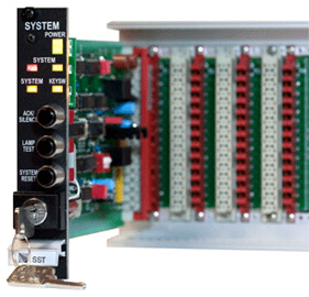
During normal operation, the green Power LED will be the only visible indication on the module. This indicates that 24 volt DC power is being supplied to the module from the redundant system power supplies. Just below this green LED is a companion yellow LED which is normally invisible. Should either of the system power supplies fail, the yellow LED will blink to indicate a power fault to this module.
When an alarm condition is detected by any module in the associated NOVA-5000 system, the red System Alarrn LED on the System Module will begin to blink. At the same time, the System Alarm Output of the System Module will be activated. This output would normally be connected to the alarm input(s) on SST Model 5241 Supervised Alarm Output Module(s) to activate audible and/or visual alarm indicating appliances (bells, horns, strobe lights, etc.). In applications where supervision of the alarm signals is not required, the system alarm output may be used to directly energize an alarm relay. The LED will continue to blink and the alarm devices will continue to sound until the Acknowledge/Alalm Silence pushbutton on the front of the module is depressed. Depressing this button silences the alarm devices, extinguishes the alarm LED on the System Facilities Module, and causes the blinking LED on the module(s) that initiated the alarm to change from blinking to steady on. This sequence is repeated every time a new or subsequent alarm is initiated.
After the alarm condition has cleared, the operator can reset the latched alarms on all input modules simultaneously be depressing the Reset pushbutton on the Model 5120 System Facilities Module. Above the Reset pushbutton, a system Lamp Test pushbutton is provided. Pushing this button will cause all module LED’s and readouts to be activated for checking.
The fourth switch on the module front panel is a two position key operated switch, which may be used for any desired function. Some typical uses for this switch are:
The Model 5120 System Facilities Module also provides capabilities for monitoring any faults in a NOVA-5000 Svstem. Upon activation of the fault bus by cmy module, an audible signal buzzer in the System Module is activated, and the yellow Svstem Fault LED on the module begins to flash. Pressing the Acknowledge button on the module resets the fault detection circuits in the module for resounding when the next fault is detected. (This does not reset the fault condition on the initiating module, unless the fault has cleared.)
The Model 5120 System Facilities Module may occupy any one slot in a standard NOVA-5000 module mounting rack.
System Alarm acknowledge, alarm reset and lamp test capability shall be provided by plug-in System Facility Module(s). The module shall include Light Emitting Diode (LED) lamps to indicate the presence of system alarm and system trouble conditions which have not been acknowledged. A dedicated system alarm output shall be provided, suitable for driving the inputs on compatible alarm output modules. The module shall also contain an internal system trouble audible signal which shall sound until system troubles are acknowledged. The System Facilities Module shall include a front panel mounted key operated two position rotary switch which can be assigned to any desired function. The operating kev shall be removable from the switch only when the switch is in the normal position. In systems with multiple System Facilities Modules, it shall be possible to have all switches operated by the same key, or to have different keys for each switch, as specified. In the latter case, there shall also be available a master key which will operate any of the system switches. Safety Systems Technology Model 5120 System Facilities Logic Modules, or approved equivalent, shall be supplied.
| Module Inputs: | Receive pulse signals from other system modules via bus structure on mounting rack backplane. No external wiring required to activate these inputs |
| Module Outputs: | Open collector current sink, 300 mA max. May be used to drive other modules, relays or indicators. |
| Key Operated Switch: | Rated 250 VAC, 24 VDC, 2 amps May be wired to provide any desired function through screw terminals on module mounting rack backplane. |
| Front Panel Indicators: | Power On, Power Fault, System Alarm, System Fault, Key Switch Operated All indicators are Light Emitting Diodes (LED’s). |
| Front Panel Controls: | Acknowledge/Alarm Silence, System Reset, Lamp Test Switches All are momentary pushbutton switches. |
| Power Requirement: | 24 VDC, 40 mA standby, l00 rnA alarm Provided by the NOVA-5000 redundant power supply systems. |
| Slze: | 0.99 inches wide, 5.06 inches high, 7.4 inches deep Requires 1 mounting space in SST standard mounting rack. |
| Weight: | 7 ounces |
| PART NUMBER | DESCRIPTION |
| 35120-1 | Model 5120 Svstem Facilities Logic Module. Key switch operates with SST standard key. |
| 20125-11 | Additional key, SST standard version, for use with part number 35120-1 modules |


 Where to Buy
 +1 (949) 583-1857