5100 Multi-Input Voting Logic Modules are used to monitor the status of a group of different input points in a hazard zone, and report when a selectable number of these points is in an alarm condition. This function is used primarily to require that more than one sensor or detector is in alarm condition prior to release of extinguishing agent into the hazard.


Logic Module is used to monitor the status of up to 14 different points in a hazard zone, and report when a selectable number of these points is in an alarm condition. The 14 inputs on the Model 5100 module are normally fed from the alarm outputs of other system modules in the NOVA-5000 System. The module provides two solid state outputs. One output is energized when any one (1) of the outputs is in alarm. The second output is energized when one (1), two (2), three (3), four (4) or more outputs are in alarm. For hazard zones that consist of more than 14 alarm points, any number of voting modules may be cascaded, so that even the largest zones can be voted.
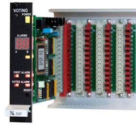
During normal operation, the only visible indication on the Voting Module is the green Power LED (Light Emitting Diode) on the front of the module. This LED indicates that the operating power from the NOVA-5000 system rack is being supplied to the module. Dual redundant sources of power are suppled to the module from the rack. Should either of these sources fail, the adjacent yellow Power Fault LED will begin to blink. This LED will continue blinking until the system Acknowledge button is depressed. At this time, the LED will light continuously if the power fault still exists, or will extinguish if the fault has been cleared.
A digital readout is provided on the front panel to indicate the quantity of points that are in alarm at any time. As long as there are no alarms, this readout will be blank (turned off), so that it is invisible. When the first input point goes into alarm, the readout will display the digit “1”, indicating that one point is in alarm. This display may be set, using DIP switches on the module printed circuit board. These switches select latch mode “0”, “1”, or “2”. “Latching” means that the maximum number of points that have reported an alarm since the module was last reset is displayed even if the alarm condition disappears at a later time. In latch mode “0” no readout numbers are latched, i.e. the readout always displays the number of alarm input points currently in alarm and goes back to blank display after the alarm condition disappears. In latch mode “1” only alarm numbers equal or greater than the programmed alarm threshold (PAT) are latched. In latch mode “3” all alarm numbers greater than zero are latched, i.e. even the occurrence of first alarms is latched. The Reset pushbutton on the module, in addition to resetting any latched indications on the module, causes all LED’s and all segments of the digital readouts to be illuminated for checking. This same function can be activated from the system Lamp Test pushbutton.
The inputs to the Model 5100 Voting Module are normally fed from the alarm outputs of other NOVA-5000 system modules. In this case, these other system modules will provide any required system alarm output capabilities. In some cases the Model 5100 may be triggered by contact closures in external alarm process monitoring devices. In this case, the module generates a short pulse signal which is transmitted on the NOVA-5000 system alarm bus every time the displayed number on the digital readout increases, thus alerting personnel to the increased hazard. This feature is selectable with a DIP switch. All connections to the Model 5100 Voting Logic Module are made to the 16 screw terminals on the module mounting rack.
System voting logic capability shall be provided by plug in module(s) having 14 independent logic inputs per module. Activation of logic inputs shall be displayed on a digital readout on the front of the module, with the readout indicating the quantity of inputs that are activated. The readout shall indicate “1” when one and only one input is activated. It shall be possible for the user to set this indication to be latching or self resetting (non-latching). Activation of subsequent inputs shall cause the total number of inputs activated to be displayed on the readout. It shall be possible to set this indication to indicate the maximum number activated since last reset, or to indicate the number of inputs activated at the current time. This setting to be independent of the “1” input setting. The module shall operate at 24 volts DC nominal. It shall be possible to cascade multiple modules with no limit to the number of inputs that can be voted in a hazard zone. The module shall include self-checking diagnostic firmware. Any failure detected during selfcheck shall cause illumination of a fault LED and appropriate fault signalling to the system busses. Safety Systems Technology Model 5100 Voting Logic Modules, or approved equivalent, shall be supplied.
| Alarm Logic Inputs: | 14 provided, 24 VDC nominal input Normally open. Connect to DC common to activate input. |
| First Alarm Output: | Open Collector current sink, 300 mA max. Activated when any one module input is active. May be connected to an input on another voting module. |
| Voted Alarm Output: | Open Collector current sink, 300 mA max. Activated when number of active alarm inputs exceeds programmable alarm threshold. May be connected in parallel with voted output on other voting modules. |
| Digital Readout: | 1 to 14 Indicates quantity of inputs activated. Readout blank when no inputs are activated. |
| Front Panel Indicators: | Power On, Power Fault, Maximum Number of Alarms, Fault All indicators are light emitting diodes (LED’s) |
| Front Panel Switches: | Reset Also performs lamp test function. |
| Internal Adjustments: | Latch mode (2), cascade mode, zone mode, alarm threshold (2), alarm pulse generation Set using switches on PC board. |
| Power requirement: | 24 VDC, 80 mA standby, 140 mA alarm Alarm current applicable when one or more inputs are activated. |
| Size: | 0.99 inch wide, 5.06 inches high, 7.4 inches deep Requires 1 mounting space in SST standard mounting racks. |
| Weight: | 7 ounces |
| PART NUMBER | DESCRIPTION |
| 35100 | Model 5100 Voting Logic Module |


 Where to Buy
 +1 (949) 583-1857