5028 Intelligent Combustible and Toxic Gas Detection Modules feature easier periodic recalibration with electronic setting of the calibration controls. Versions are available for use with Catalytic sensors, or any other combustible or toxic sensor having a 4-20 ma output.


The SST Model 5028 Intelligent Gas Detection Modules, when connected to suitable combustible or toxic gas sensors, monitor the gas concentrations in a protected area.
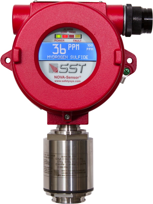
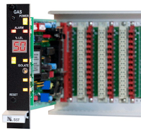
During normal operation, only the green Power LED and the digital display indicating gas concentration are visible on the module. Combustible gas modules display the concentration as a percentage of the lower explosive limit of the gas (0 to 100% LEL). Toxic gas modules dieplay the concentration in parts per million. The range for toxic gasses is switch selectable to 10, 20, 50, 100 or 200 PPM. Associated with the display are two independent alarm trip circuits. The trip point for either circuit is set to any desired value. When the level of gas detected passes the trip points, the red A1 (low) or A2 (high) LED will illuminate, and the modules low or high alarm relay is energized. At the same time, a short pulse signal is sent on the main system alarm bus to initiate an external alarm signal. If the alarm circuits are set to be “latching,” alarm indications and outputs remain until the Reset switch is depressed. The A1 alarm may also be set to non-latching so that it automatically restores when the gas concentration decreases below the trip point. During normal operation, the sensor wiring connected to the module input terminals is continuously “supervised” for faults. The supervised circuit will cause the yellow fault LED to illuminate if any field wire is open, shorted, or drawing excessive current. Any power failure will be indicated by illumination of the yellow power fault LED.
Depressing the Mode switch on the front of the module, when no alarm is in effect, will momentarily display the LOW and HIGH alarm trip point settings in the module. The mode switch can also be used to initiate the module calibration routine. If the calibrating gas is now applied to the gas sensor, the digital readout, alarm LED’s and lamp outputs will function normally. However, the alarm relay outputs will not be activated. During calibration, the green CALIB LED flashes, and calibration data is automatically stored in the module’s nonvolatile memory.
In addition to the features noted above, all LED’s will be illuminated when the LAMP TEST bus input is activated. Each module mounts in one plug-in space in the NOVA- 5000 Rack Assembly.
Gas detection capability shall be provided by plug-in module(s) with associated gas detectors, suitable for detecting (name of combustible gasses in concentrations from 0 to 100% LEL) and/or (name of toxic gasses in concentrations from 0 to 10, 20, 50,100 or 200 PPM). The module shall be capable of supplying operating current for the sensor devices. The field installed wiring between the module and field device shall be continuously supervised, and a fault reported upon detection of any open or short circuit. Alarm and fault conditions shall be indicated by LED’s on the front of the module. The module shall provide a front panel mounted MODE switch which enables calibration and testing of the alarm circuits in the module without activating the system outputs from the module. It shall be permissible to insert or remove the module from its mounting rack without removing power from the rack, and the manufacturer’s literature shall so state. Safety Systems Technology Model 5028 series Intelligent Gas Detection Modules, or approved equivalent, shall be supplied.
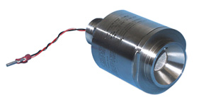
| Catalytic Sensor Input: | 300 mA heater current for 3-wire active bridge circuit Applies only to part number 35028-1 |
| Current Sensor Input: | 4-20 mA current input 0.2 volts maximum voltage drop Applies to part numbers 35028-2 or -3. Suitable for any loop powered sensor that provides a 4-20 mA output. |
| Relay Outputs: | A1 (low) Alarm, latching or non-latching A2 (high) Alarm, latching |
| Alarm Relay Contacts: | 1.0 Amp @ 28 VDC Resistive One set for Low Alarm, one set for High Alarm. Connect to 3 screw terminals on backplate, NO, COM, NC. |
| Solid State Alarm Outputs | Open Collector current sink, 300 mA max. Follows state of alarm relays on module. |
| Analog Output: | Module will source 0 to 20 mA DC into a load of 600 ohms or less Can be used to transmit current at sensor input to external equipment. |
| Digital Readout: | 0 to 100% LEL or 0 to 10, 20, 50, 100 or 200 PPM Display resolution is 0.1%. |
| Front Panel Indicators: | Power On, Power Fault, Low Alarm, High Alarm, Calibrate running, Mode, Channel Fault All indicators are Light Emitting Diodes (LED’s). |
| Front Panel Switches: | Mode pushbutton (Reset) |
| Internal Adjustments: | Alarm trip level set pushbuttones (up, down) Trip levels set digitally and remembered in microprocessor. Extender card required to adjust levels. |
| Power Required: | 24 VDC nominal 180 mA standby, 125 mA alarm (catalytic version) 80 mA standby, 140 mA alarm (all others) Catalytic ratings include current required by sensor. Add required sensor current for other versions |
| Size: | 0.99″ wide x 5.06″ high x 7.4″ deep Requires 1 mounting space in SST Standard Mounting Rack. |
| Weight: | 7 ounces |
| PART NUMBER | DESCRIPTION |
| 35028-1 | Model 5028 Intelligent Gas Detection Module, combustible for use with GC800 or GC802 Catalytic Sensors |
| 35028-2 | Model 5028 Intelligent Gas Detection Module, combustible for use with GC801, GIR900, GIR901 or other 4-20 mA sensors |
| 35028-3 | Model 5028 Intelligent Gas Detection Module, toxic for use with sensor ranges 10, 20, 50, 100 or 200 PPM |
| 35360 | Module Calibration and Test Extender Card (required for field setting of trip points) |


 Where to Buy
 +1 (949) 583-1857